Brassac GREC Lab Model v2
This is a short description of the parts of the Brassac Green Revolution Energy
Converter Lab Model v2, now under construction and almost all parts are already
manufactured in Brassac France. Assembly started in Motala Sweden and is continued
at FabLab in Brassac.
 |
The first version of the GREC Lab Model
delivered very promising but non documented results. When we opened it up to
provide it with syncronised sensors for temperature and pressure, we decided to
put in new Revolving Shutters as well.
But finally it was easier to build a
completely new Lab Model instead. We updated all our FreeCAD dxf drawings and in
autumn 2018 we started to manufacture a completely new set of parts using the Brassac
FabLab high precision CNC cutter. Click this link to see
current status of the project.
Below are the original 3D generated images that we used when updating our .dxf files
for the FabLab CNC cutter and also photos of the resulting machined parts. |
Starting with the "End Plate"
 |
First 3D generated image is the 600x600x10mm end plate with a circle of holes to keep
the construction together but also to be sure that all added layers will be
perfectly aligned. The centre hole for the roller bearing is cut at the same
time. Download Shell600GabaritHoles_a.dxf here. |

| |
We used a blue composite material
for the "End Plate". The centre hole holds its
SKF roller bearing and some of the holes in
the peripherial circle have a screws inserted.
(Sorry for the conflicting colours between the 3D sketch and the real model)
|  |
Building the first layer of insulating and conductive "Fins"
 The Green Revolution Energy Converter is built in
layers. The layer following the "End Plate" is
a layer with heat conductive and insulating fins.
This scematic 3D generated image shows adding
two 6 mm insulating "Nil Fins" for insulation
between the heat conductive fins of the cold and
the warm side of the Green Revolution Energy Converter.
In this version of the Lab Model we have choosen
to integrate the first layer of fins directly in
the endplate (see photographic images)
The Green Revolution Energy Converter is built in
layers. The layer following the "End Plate" is
a layer with heat conductive and insulating fins.
This scematic 3D generated image shows adding
two 6 mm insulating "Nil Fins" for insulation
between the heat conductive fins of the cold and
the warm side of the Green Revolution Energy Converter.
In this version of the Lab Model we have choosen
to integrate the first layer of fins directly in
the endplate (see photographic images)
Adding two conducting fins at the same layer as the insulating fins. The
conducting aluminium fins will be the area that transfer heat in and out of
the "Work Generating Volume". Both of the conducting fins are made of 6mm
aluminium as seen in the photograph, and they will be gued in place. The
3D image has conducting aluminium fins in colours blue and red to mark out
that one is situated
on the cold side (blue) and the other one on the warm side (red). Again, so
sorry for the conflicting colours between the 3D images and reality. In this Lab Model we
decided to make them a bit longer so we can “interface” with
external cold and hot sources. Download conducting fins
here .
Building a layer to contain a "Work Generating Volume"
 When you look close at this picture there are "Nil Shells" on top of the
fin layer. Download the nil
shells here .
When you look close at this picture there are "Nil Shells" on top of the
fin layer. Download the nil
shells here .
The nil shells will create the boundary of the system volume
together with the conducting shells that you may see in the following 3D
generated image.
Both the nil and the conducting shells will be glued
on the fin layer so the "End Plate", the "Fin Layer" and the "Shell Layer"
will become one unit.
The conducting shells, blue and red, will complete the system volume boundary. They
are both identical and made of aluminium. Download the conducting shells here.
Looking at the photo you will confirm that both the conducting
shells and the nil shells are placed on top of the conducting fins. They
will be glued in place at a later moment.

|

|
Adding the Revolving Shutter
Both 3D image and the photo shows a grey Revolving Shutter. The quarter
opening of the Revolving Shutter is the most important detail of them all!
This important opening is the Work Generating Volume. This is where it
all happens. On the warm side the pressure mounts in the Work Generating
Volume resulting in higher pressure of the whole GREC System Volume and
when the Work Generating Volume is on the cold side the
pressure drops within the whole system. Download the Revolving
Shutter .dxf here.
Building a second "Fin-Layer"
 The following 3D images shows how we add the middle layer of fins starting with the nil
fins and then adding the conducting fins.
The following 3D images shows how we add the middle layer of fins starting with the nil
fins and then adding the conducting fins.

|

|
The photo shows the middle layer. Note the pre-manufactured traces for
sensors (temperature and pressure) and electrical wires. Also showing
two spools of Teflon coated wiring that we will use. |
Building a second layer to contain an additional "Work Generating Volume"
Starting with the boundary shells on top of the fins.
And adding a Revolving Shutter giving the second layer a Work Generating Volume.
Finally sealing it all with a "Layer of Fins" and an "End Plate"
An additional layer of fins to transfer heat in and out of
the Work Generating Volume of the Revolving Shutter.
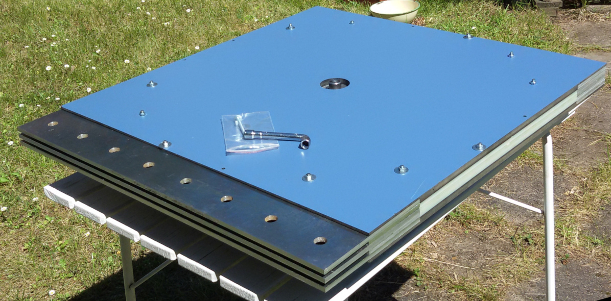
 Photo shows layer side up of the integrated "End Plate". We just have to
turn it, fit the roller bearing and start fit screws in the circle of holes
to seal the complete system volume.
Photo shows layer side up of the integrated "End Plate". We just have to
turn it, fit the roller bearing and start fit screws in the circle of holes
to seal the complete system volume.

The GREC system boundary is finally sealed by an End Plate on top
of the last layer of insulating and conducting fins.
By fitting it all together and using an electrical motor
to turn the revolving shutter the GREC Lab Model v2 will start to deliver
real world values on pressure difference in relation to rotation speed and
temperature difference so that anyone can calculate on its usefulness in
their applications. That’s it!
Bill of Material for CNC
To conclude, a parts list of the Brassac GREC Lab Model version 2 with
downloadable CAD files in .dxf format,
click on the corresponding icon to download :
Note: The download attribute is not supported in IE, Safari or Opera version 12 (and earlier).
Good luck in building your own Green Revolution Energy Converter
supplying you with lots of free energy!
Click this link to go to the nilsinside
PROJECT page.
updated by KITS