The computer 3D model geometry is now available in different mesh and solid
file formats that facilitates computer aided simulations like Computational
Fluid Dynamics (CFD) and others.
By using and comparing GREC Lab Model "reality" results with (several) general
theoretical simulations we will be able to tune the pulsating heat transfer
in the Green Revolution Energy Converter (GREC) and also to be able to
evaluate all future Green Revolution Energy Thermal Applications (GRETA)
awaiting to take off.
The convective heat transfer coefficient for a turbulent flow is relatively
high compared to the low coefficient for a laminar flow. How this affects
the GREC pulsating power is very important but not fully understood in
this revolving concept. Studying both the GREC Lab Model and the GREC 3D
Computer Model will shed some light on this and answer questions like: How
does different fluids deliver their pulses? How will existing heat storage,
natural or man made or combination thereof, deliver kinetic energy? How
does partial or full phase shift of a working fluid affect pulse output?
Today we assume that the theoretical maximum of energy available to
harvest in the GREC is calculated by the amount of energy that we may
store in a cycle in the fluid of the Work Generating Volume multiplied
by the number of cycles per second.
The lion part of the total working fluid in the GREC is situated in the
open sector of the Revolving Shutter (RS) and this part is the Work
Generating Volume (WGV). Other parts of the fluid, i.e fluid NOT situated
in the WGV, is called the dead volume or inactive volume. The dead volume
is a minor part of the total fluid volume. When the WGV is revolving, a
part of the dead volume is situated between the Revolving Shutter disc
and the system limit in a laminar flow. This minor “dead” volume still
has important functions but it also interacts with the system in a way
that has not yet been mapped.
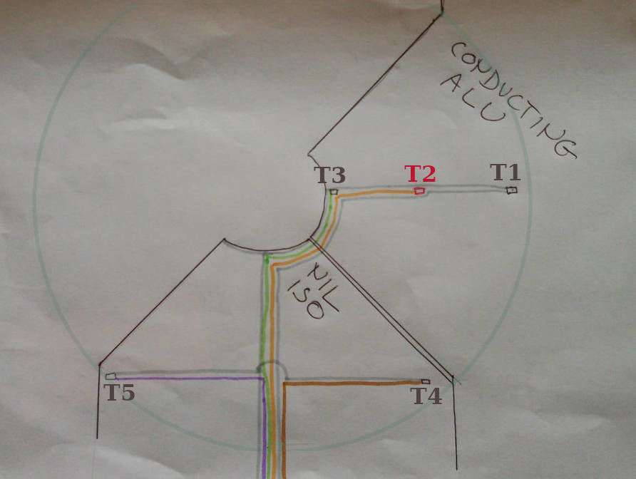
Sitting on a hot fin: The video above visually describes how we
enter inside the GREC 3D Computer Model and sit down in the centre of the
image on the fixed point T2 on the hot conductive fin while the Revolving Shutter with its WGV
passes in the upper part of the image. As described in the sketch
below there are three pt500 thermistors on the conducting fin measuring
the metal surface temperature mean values. T1 is on the peripheral circle
of the GREC closed volume boundary, our point T2 (red) is radially middle
of the surface and T3 is close to the centre of the GREC:
Hot side, turbulent flow, convective heat transfer, HIGH heat transfer
coefficient: Back in the video, the Revolving Shutter (RS) exposes
the turbulent swirling gas of the Work Generating Volume (WGV) to the
conducting fins for 1/4 of a revolution. The video clip shows the turbulent
high heat transfer coefficient swirl of the WGV that quickly turns from cold (blue)
to warm (red) while it passes our fixed point T2 on the hot conducting fin.
During this 1/4 time space, the hot fin surface transfers heat into the
Work Generating Volume. The hot fins has to contain the heat needed for
the convective transfer to heat up the WGV to a temperature close to the
hot fin surface temperature.
Hot side, laminar flow, convective heat transfer, LOW heat transfer coefficient:
While the Work Generating Volume (WGV) continues to travel the remaining 3/4
of the revolution, the video clip shows the solid part (black) of the RS displacing
the gas while passing over the conducting hot fin
surface resulting in a laminar flow (grey horizontal line) between the Revolving Shutter
and the fin. This laminar flow with a low heat transfer coefficient allows
the conducting fin to recharge energy, i.e. warming up its surface again
for 3/4 of the time before the next 1/4 turbulent exposure.
The cold side, turbulent and laminar flow:
The same calculation and reasoning could be valid on the cold side as well.
To get an estimate we assume, for the time being, that the results of cooling
down the WGV follows a similar reasoning, so we have postponed these
calculations during these first general simulations and approximate the
cold side by just changing the appropriate signs. (Underlining for the
time being, since there are objections).