Pulsating Heat Transfer – Reality
Analyse of a Carnot engine, video clip VID-20170511-WA0016.mp4, where an
electric motor is used to revolve its "Work Generating Volume" between a
hot and a cold storage. The video is used to analyse the generated pressure
pulses. (Th 40,5 Tc 12,5 delta 28 degrees)
First experiments show the revolving technology to be extremely efficient,
and it also shows its aibility to convert even low temperature gradients into mechanical energy.
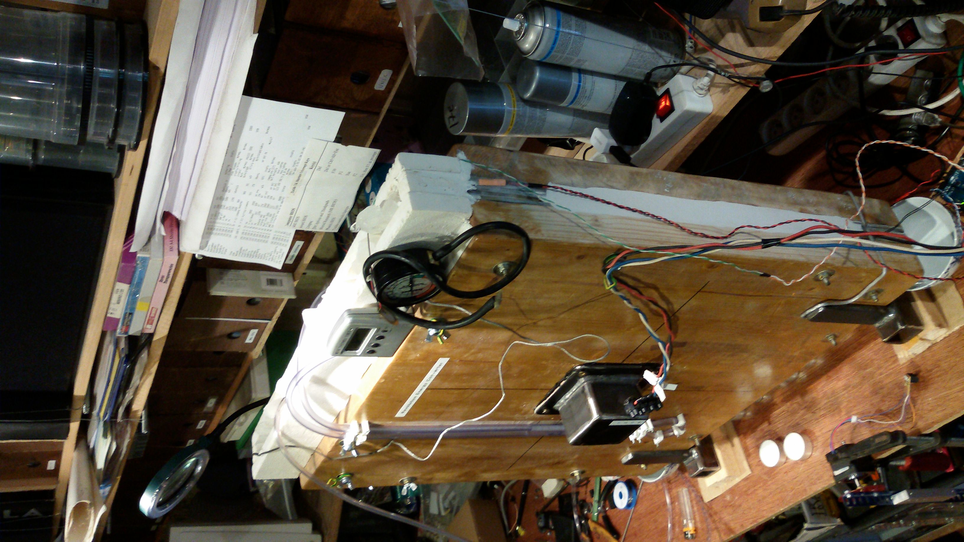
Experimental Thermal Application Setup:
Hot Storage side, Th = 40.5 °C
Cold Storage side, Tc = 12,5 °C
Temperature Gradient, ΔT = 28 °C (28 °K)
Total Gas Volume about 0.85 l (850 cc)
Work Generating Volume 0.32 l (320 cc) ( <=> Dead volume 0.53 l)
Stepper Motor Revolving Speed 1,5Hz = 90rpm
The very first analyses of the video shows the revolving technology
to be astonishing fast and efficient.
We were not really expecting this with such a small Work Generating Volume being
only 37% of the total gas volume in the closed system.
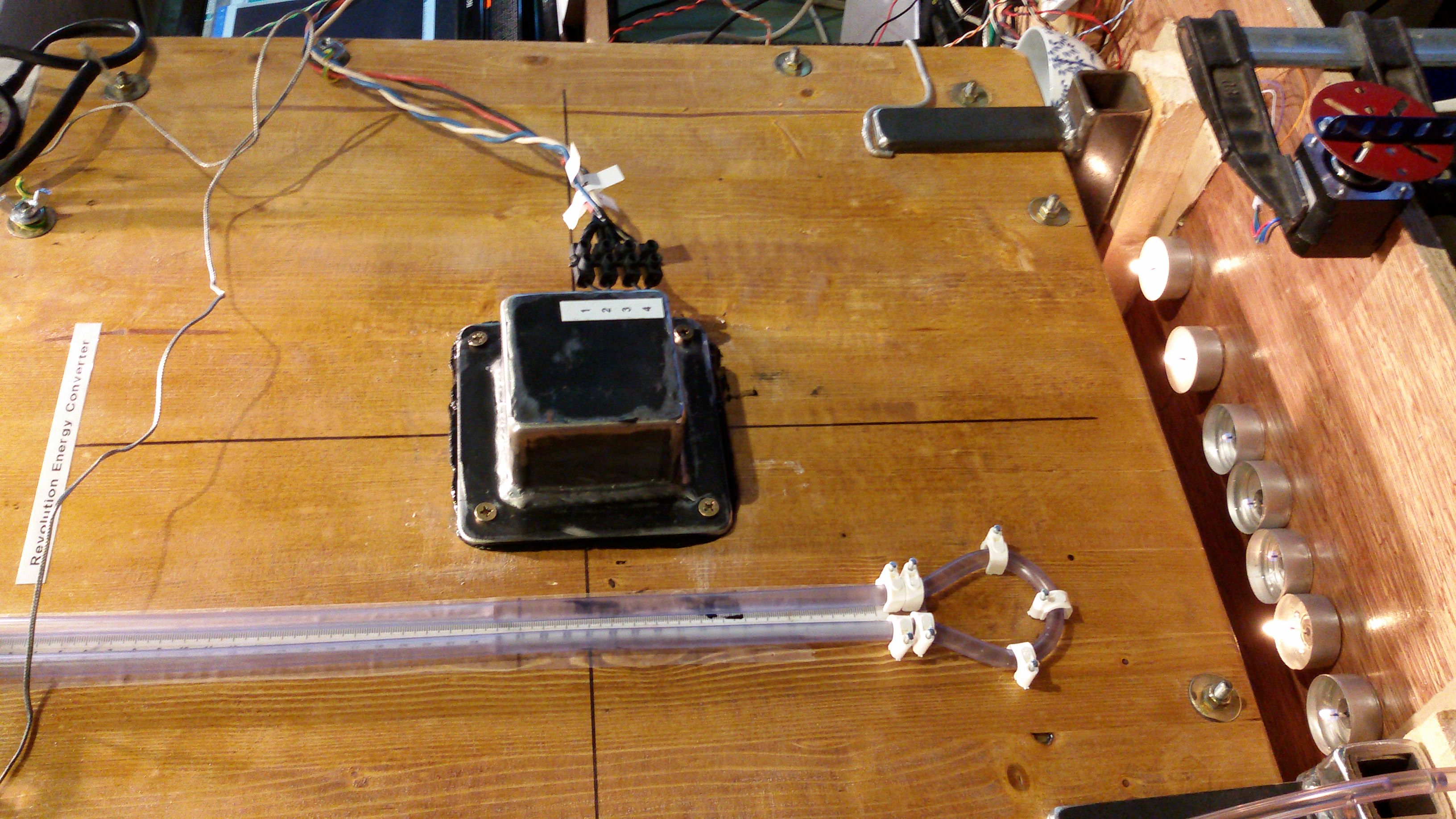
In this video above you hear the noise an electric stepper motor that moves
air between a hot and a cold space. At the same time you see a vertical
transpaerent plastic U-Tube Manometer with ink-coloured water reflecting
the pulsating changes in pressure and volume of the air inside the closed
system as the air revolves between the warm and the cool side like in this
animation below:
Thermal Application setup between a Hot Storage, Th, to the left (red) and
a cool storage Tc (blue) to the right with a revolving pizza sliced
"Work Generating Volume" of air (gas). When the air revolves between
the hot and and the cool side it generates pressure pulses by repetedly
heating up, turning red, and cooling down, turning blue.
First experiments show that this seems to be an extremely efficient heat
engine that also converts low temperature gradients into mechanical
energy. The very first analyses of the video shows the revolving technology
to be astonishing fast and efficient.
The video results in a diagram that shows that even minor temperature differences may generate valuable
emission-free, sustainable and clean energy. This will hit the energy market
and the supply of energy will no longer be priced and governed by the policies
of the fossil market.
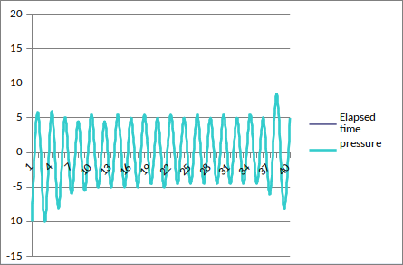
Pressure Pulses Diagram:
Counting video frames to estimate speed:
From 280 to 580 frames is 300 frames that correspond to 10 seconds
counting 15 turns calculating a speed 1,5Hz = 90rpm
(pressure is cm water column, 1cm water is 98,0665 Pa)
Hot side, turbulent flow, convective heat transfer, HIGH heat transfer
coefficient: Back in the video the turbulent swirling gas of the Work
Generating Volume (WGV) is exposed by an invisible Revolving Shutter (RS) to the
conducting fins for 1/4 of a revolution. At a slow revolution with a
more precise measurement this will result in a diagram with a square wave form.
Revolution Energy Converter Lab Model Considerations:
Work Generating Volume
The lion part of the total working fluid (air/gas) should ideally be
situated in the open sector of the Revolving Shutter (RS) and this part
is called the "Work Generating Volume" (WGV). In this simple Lab Model
the Work Generating Volume is ONLY 37% of the total gas volume.
Dead Volume
The part of the total working fluid volume NOT situated in the WGV, is
called the "Dead Volume" or inactive volume.
The dead volume should ideally be a minor part of the total fluid volume.
This minor “dead” volume still has important functions and it also interacts
with the system. When the WGV is revolving, a part of the dead volume is
situated between the Revolving Shutter disc and the system limit in a
laminar flow. All effects of the dead volume has not yet been mapped and
understood.